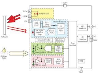
30+ proximity sensor block diagram
Proximity Sensor Block Diagram. One transducer emits 40kHz sound while the other receives 40kHz.

Capacitive Proximity Sensor Provides Accuracy And Speed Electronic Design
A 3-wire inductive proximity sensor is an electronic device that can detect ferrous Fe targets without any physical contact.
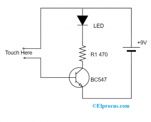
. The high-level design of the proximity detector circuit is broken into three parts. Using a Relay and IC 741. The transmitter of this circuit consists of a 940nm IR LED IR11-21C.
To turn ON and OFF the IR LED the a 10kHz oscillator frequency. Get The Latest in Product Technology. IPS can increase reliability of.
It is extensively used but it suffers from high residual voltage and leakage. Capacitive sensors are relatively slower than inductive sensors. The speed is in the range of 10 to 50Hz.
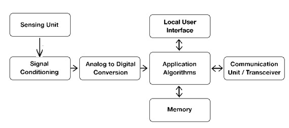
The inductive proximity sensor IPS is applicable to displacement measurements in the aviation field due to its non-mechanical contact safety and durability. A smart sensor is a device that uses a transducer to gather particular data from a physical environment to perform a predefined programmed function on the particular type of gathered. Our integrated circuits and reference designs enable you to build smaller and more integrated proximity sensors while increasing the power budget in loop-powered applications by utilizing.
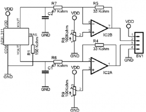
This is because it involves charging the conductive plate in the sensor. Block diagram of proximity sensor. Figure 2 Proximity sensor circuit electrical schematic.
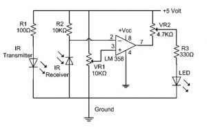
Because the sensor is an electronic device it requires a DC power source. Proximity Sensor with a Relay and IC LM358. The two-wire proximity sensor is simple to install and connect.
Lets discuss the functional block diagram of the inductive proximity sensor from sensing to output. A typical sensor that has an operating voltage of 10-30V and a detection. When it detects that target it operates an internal electronic switch.
This proximity detector works at a frequency of 40 kHz. It uses two specially made ultrasonic transducers. 2 Accurate Proximity Detector Circuit Immune to Sunlight The Circuit Concept.
Join thousands of engineers who never. How it work. Join ResearchGate to access over 30 million figures and 135 million publications all in one place.
Jump to Page Section. According to the structure type. Proximity sensors are being used in industry today to replace devices.
Here is the schematic diagram of the IR proximity sensor. 43 30 East West Highway Bethesda MD 20814. Back to top expand_less.
Smart Sensor Block Diagram Working Types Its Applications
Qph Cf2 Quoracdn Net Main Qimg Dba805cbd8ab90afe1d
What Are Different Types Of Sensors With Circuits

How Track Circuits Detect And Protect Trains Greater Greater Washington Model Railway Track Plans Model Trains Model Train Layouts
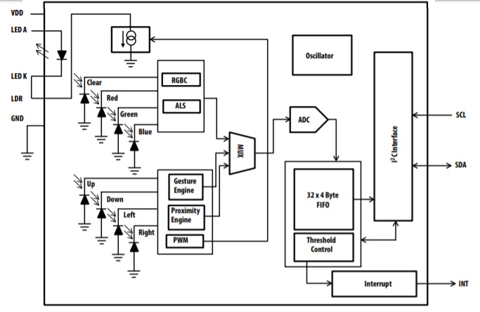
Apds 9960 Pin Diagram Specifications And Applications
![]()
Ir Sensor Circuit Diagram Types Working With Applications
What Are Different Types Of Sensors With Circuits
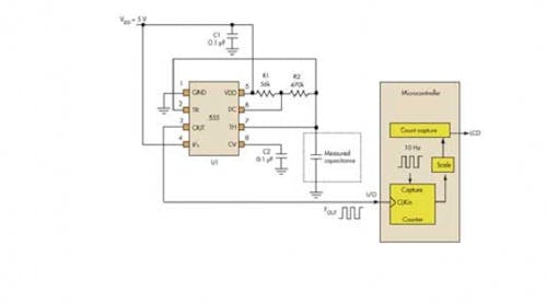
Use Analog Techniques To Measure Capacitance In Capacitive Sensors Electronic Design
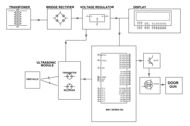
Ultrasonic Object Detection Circuit Using 8051 Microcontroller
2
Ir Sensor Circuit Diagram Types Working With Applications

What Is A Circuit Diagram Of Proximity Sensor Quora
11 Myths About Als Proximity Sensors Electronic Design

Inductive Switch Improves Reliability Of Proximity Sensing Electronic Design

Mechatronics Engineering Interfacing Lcd Without A Potentiometer In Arduino And Ccs Arduino Mechatronics Engineering Mechatronics
2

Control Fan And Light Using Tv Remote Esquemas Eletronicos Diagrama De Circuito Electrico Circuito Eletronico